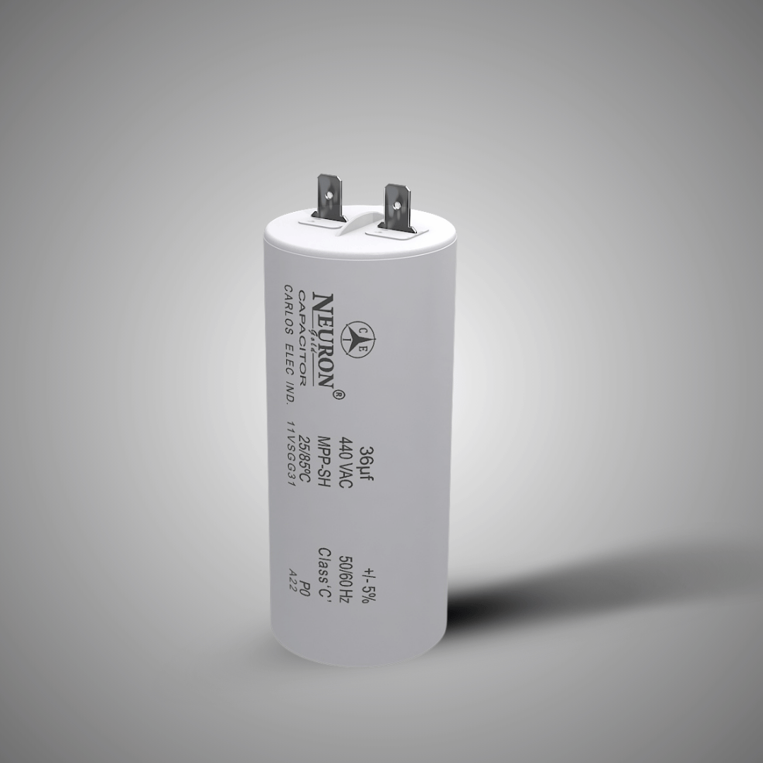
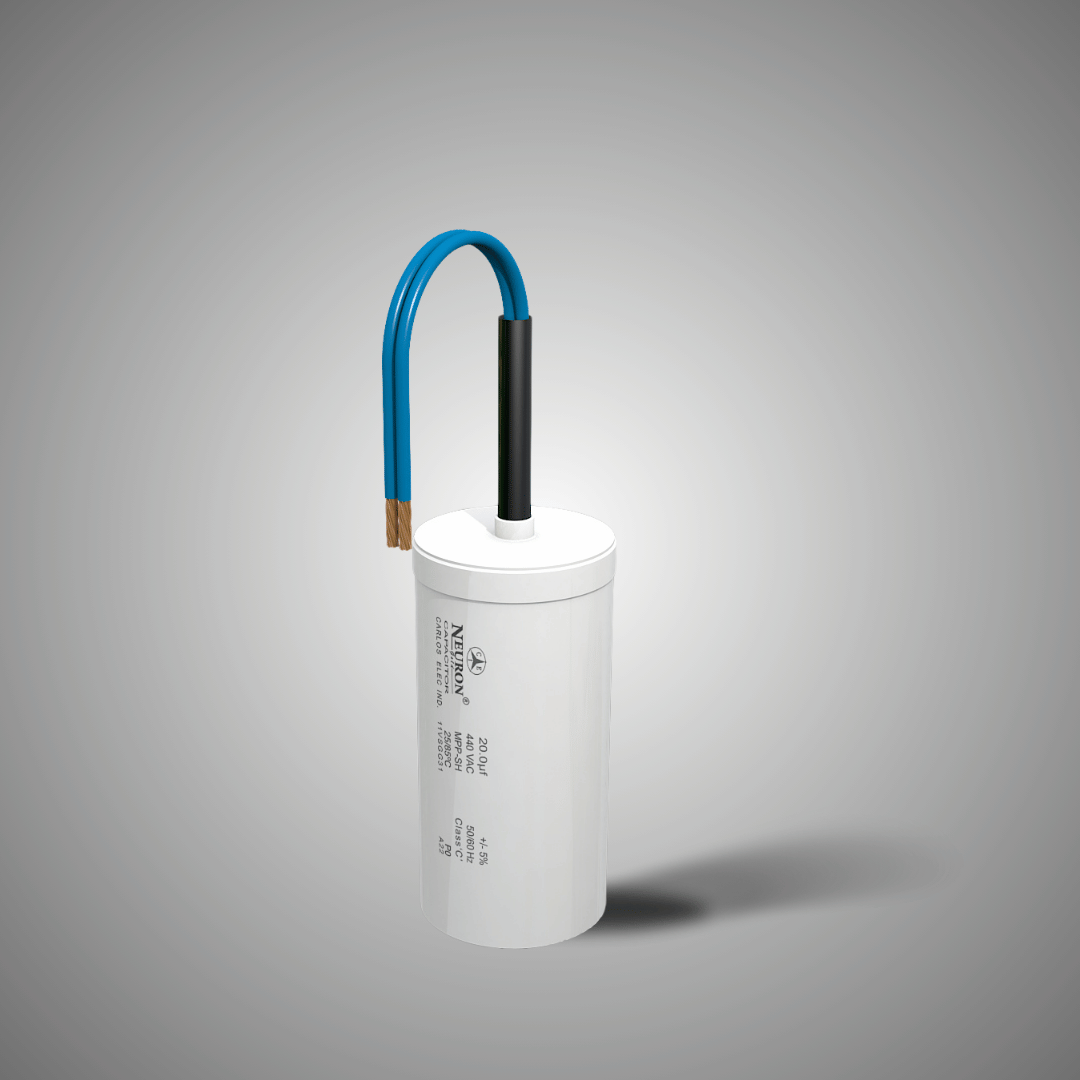
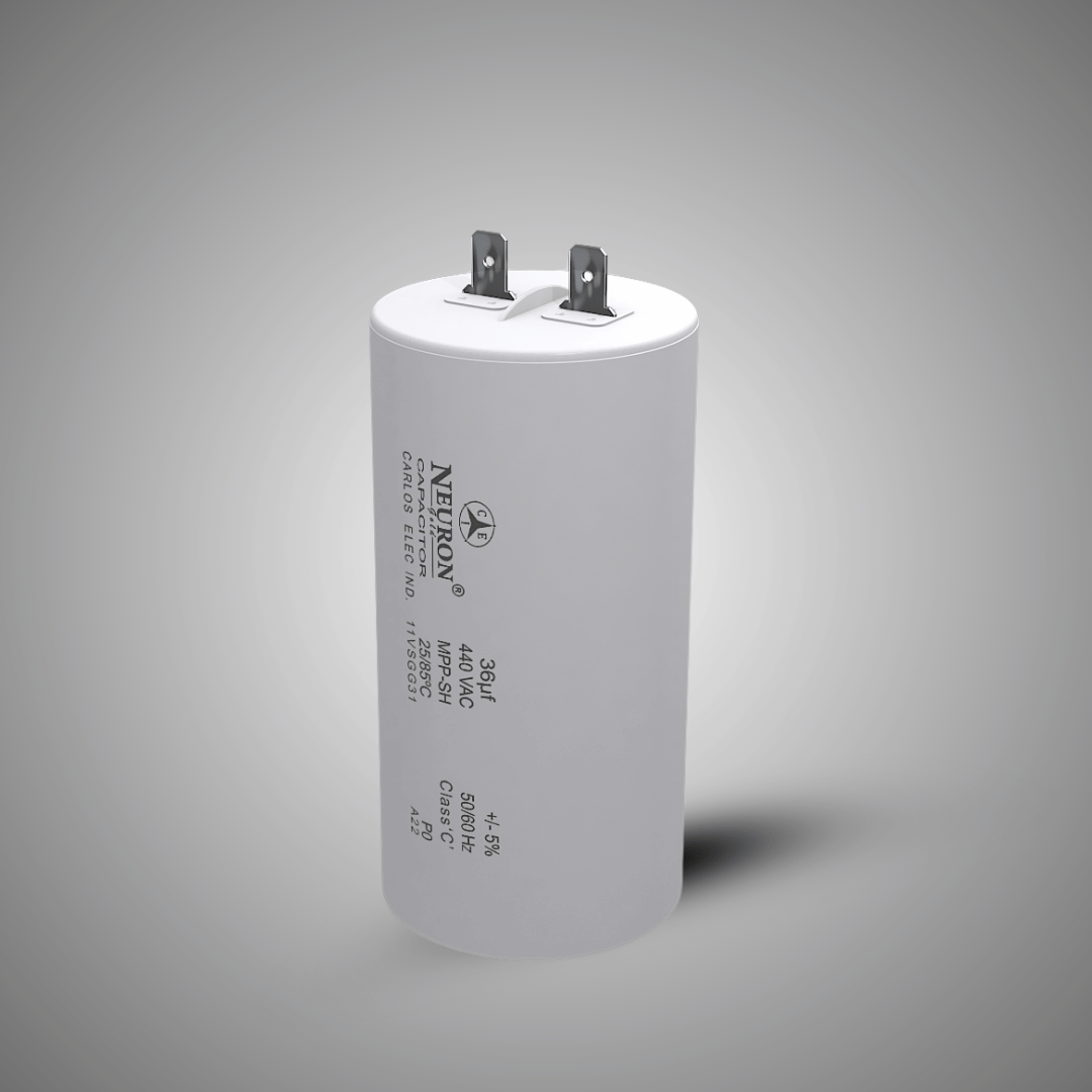
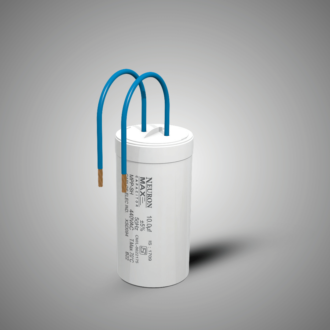
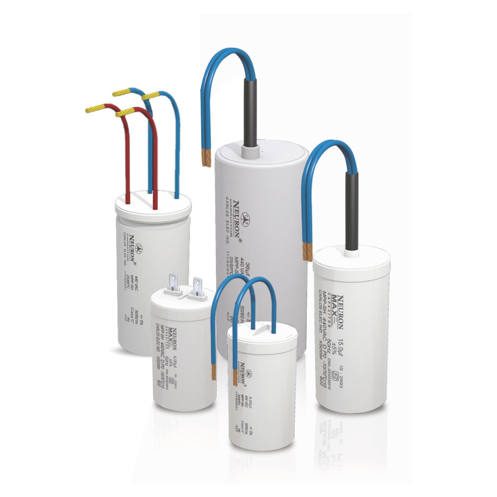
Wire / Lug Type - Motor Run Capacitor
- The capacitor is connected for the entire time the motor is in operation. The capacitance must not be too high to avoid overloading the auxiliary winding, as a result of which the starting torque is generally between 50-70% of the rated torque.
- The motor can, however, achieve performance levels equal to 90% of the rated power of a similar three-phase motor and a power factor close to 1.
- The capacitors, generally film type, chosen for this application must have a higher overload capacity, low losses, thermal stability and more silent mechanical and acoustic operation.
CONSTRUCTION:
- Dielectric polypropylene film with heavy edge
- Plastic / Aluminium can and top
- Filling material: PU Resin
TYPICAL APPLICATIONS:
- For general sine wave application, mainly as motor run
MOUNTING PARTS:
- Threaded stud at bottom of can (M8) as option
Mechanical and thermal properties of terminal insulator material
- Terminal insulation plastic material
- UL 94 (Ed6, 2013) compatible
- Compliance to Glow wire test as per IEC60335-1 (Ed6, 2020)
- Compatibility to RoHS Compliance to directive 2011/65/EU
FEATURES:
- Self-healing properties
- Low dissipation factor
- Available with segmented / pattern film
Design which ensures S0 - S3 safety - High insulation resistance
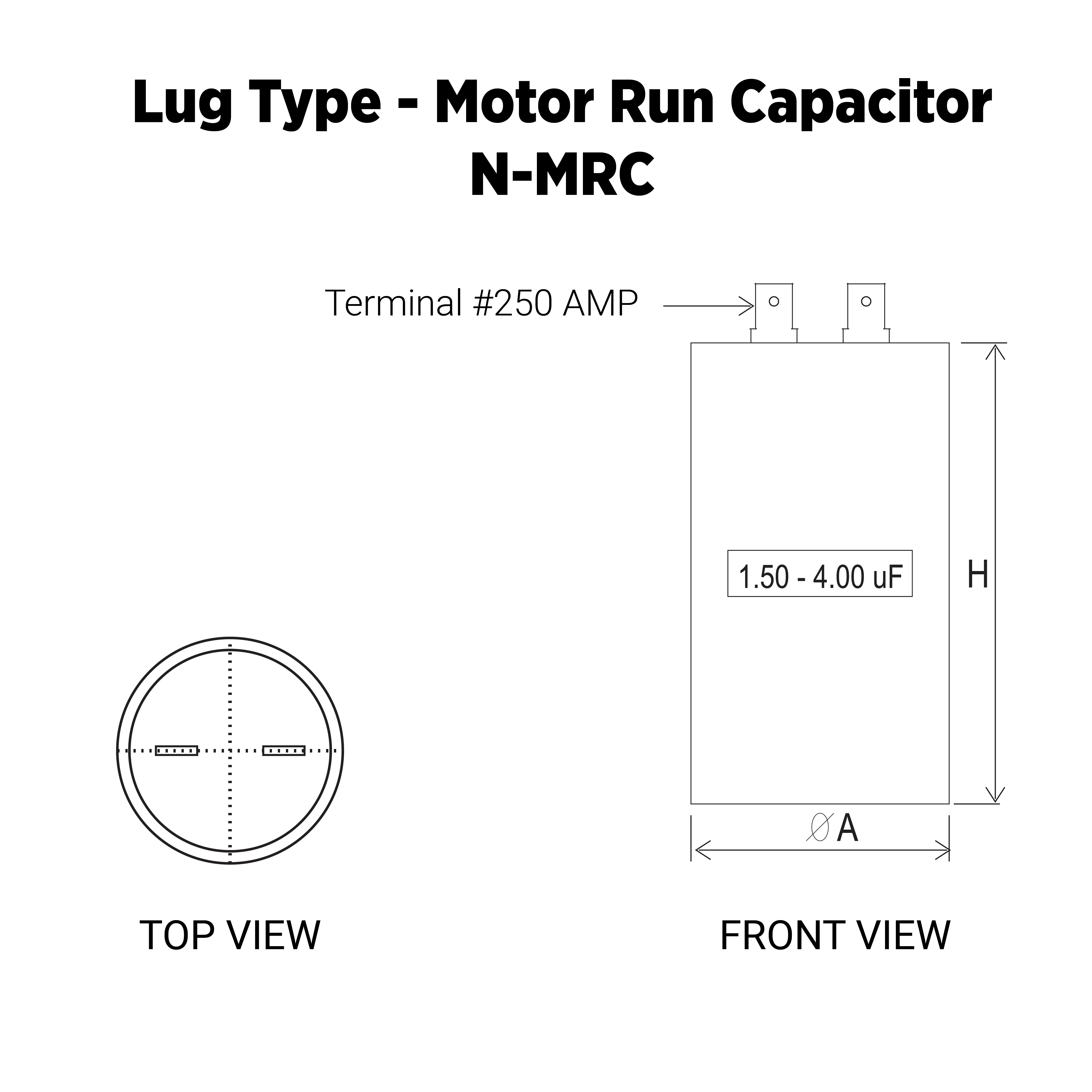
TERMINALS :
- 1+1 fast-on terminals
- 2+2 fast-on terminals
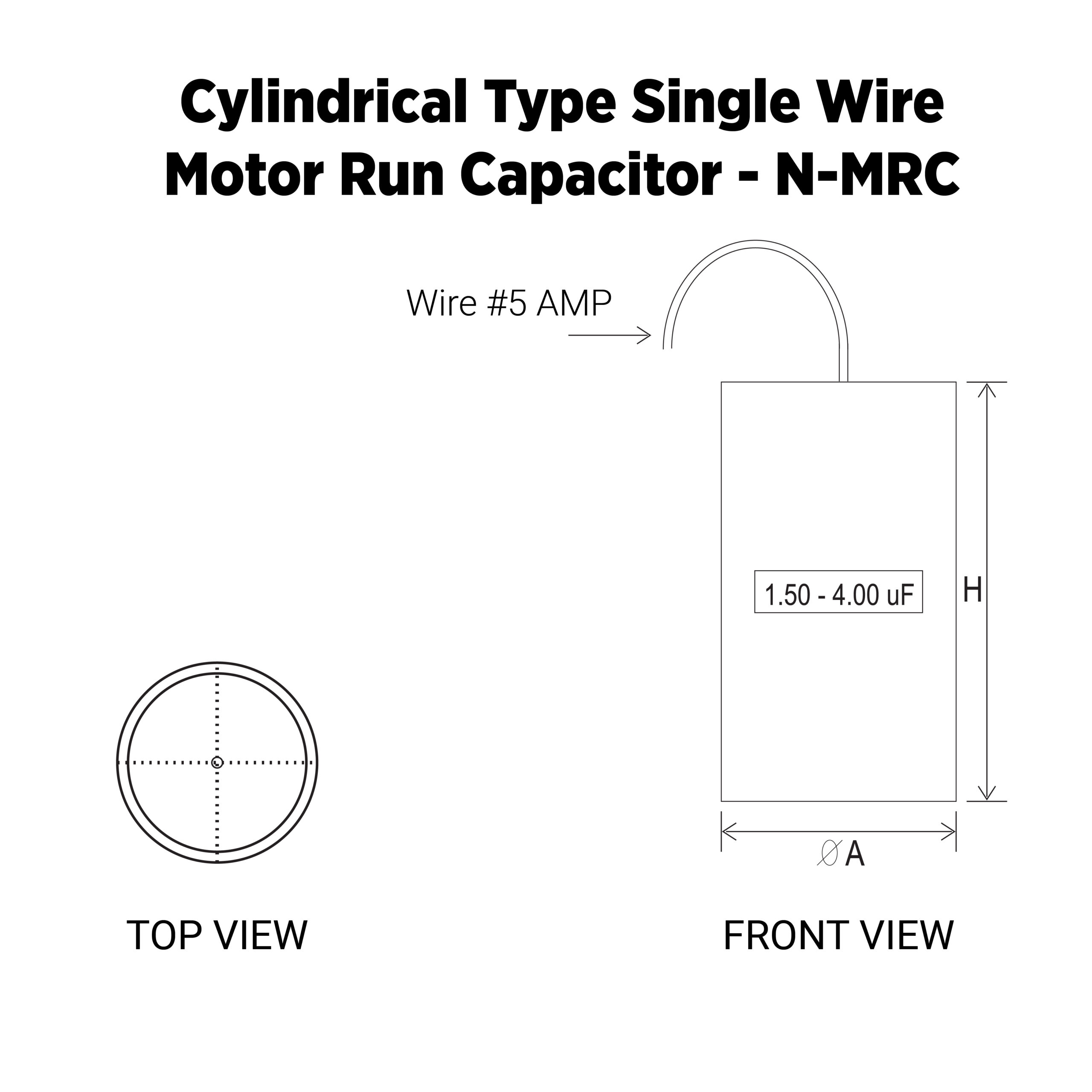
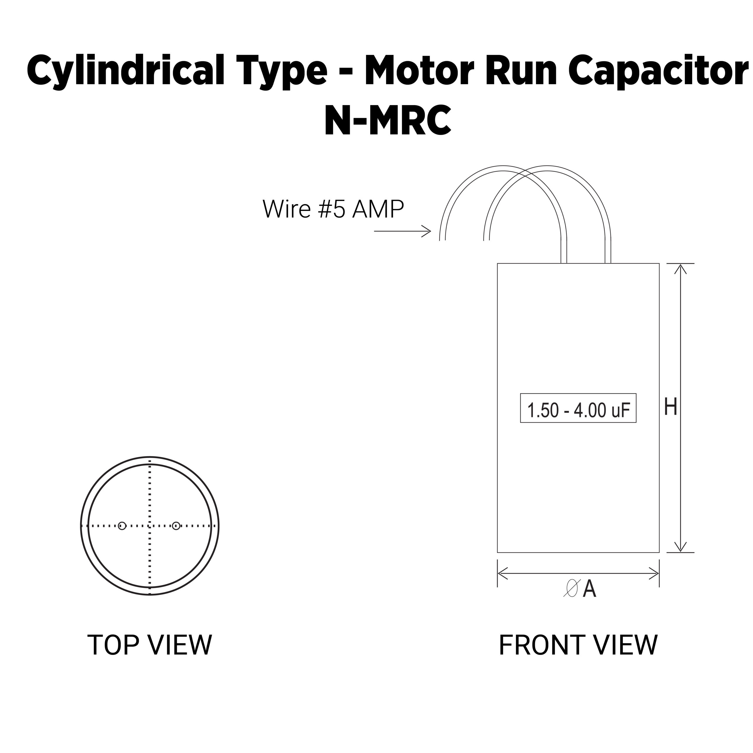
- Flexible Lead wire / Lug Type
- Insulated Cable or Lead wire with sleeve
APPROVALS:


-
TECHNICAL SPECIFICATIONS
Reference Standard
IEC 60252 ; IS 2993 ; UL 810Safety class to IEC 60252-1:2010
S0 – S3Life expectancy to IEC 60252-1:2010/AMD1:2013
450 V : 10000 h (Class B/Class B)UL 810
Approved componentRated capacitance CR
0.5 uF to 100 uF ;Tolerance Tx
± 5%,Rated voltage Vrms
440/500/600 V AC, others on requestRated frequency fR
50/60 HzElectrical Test
AC test voltage terminal to terminal VTT, rel.
2.0 X VR, 2 s (routine test)AC test voltage terminal to can VTC
2000 V AC, 2 s (routine test)Insulation resistance Rins or time constant at 20 °C Humidity ≤ 65% (minimum as-delivered
values)
10000 OhmsDissipation factor tan δ at 20 °C
≤ 2 x 10⁻³ (1 kHz)Maximum rate of voltage rise dV/dt
max 10 V/ µsClimatic Data
Climatic category
40/85/21Lower category Tmin
–40° CUpper category Tmax
+70/85° CDamp heat test ttest
21 days
N-MRC SERIES